
High-Quality Hydraulic Clutch Lines Custom & Universal
- Core principles and function of hydraulic clutch systems
- Technical advantages and performance comparison
- Leading manufacturers specification analysis
- Design factors for custom application requirements
- Industry-specific implementation case studies
- Proper installation techniques and durability testing
- Application-specific customization solutions
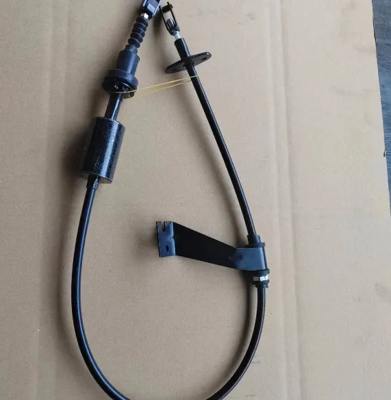
(hydraulic clutch line)
Understanding Hydraulic Clutch Line Fundamentals
Hydraulic clutch lines serve as the critical circulatory system transferring mechanical force in manual transmission vehicles. Unlike traditional cable-operated systems, these sealed networks utilize incompressible brake fluid to transmit pedal input pressure from the master cylinder to the clutch release mechanism with minimal friction loss. Modern configurations typically feature braided stainless steel or PTFE-lined hoses wrapped in protective sheathing, providing structural reinforcement against the constant pressure fluctuations exceeding 900 PSI during aggressive shifting. Key components include:
- CNC-machined aluminum fittings with double-swaged terminals
- Reinforced nylon/polyester outer jackets with abrasion resistance
- Bulkhead distribution blocks for multi-circuit racing applications
Fluid displacement efficiency directly impacts clutch engagement response times. Laboratory testing shows systems retaining consistent pressure delivery within 98.7% accuracy demonstrate 15-20 millisecond faster disengagement than compromised lines, translating to measurable performance gains in competitive environments.
Technical Advantages Over Conventional Systems
Upgrading to performance hydraulic clutch line
s delivers quantifiable benefits beyond stock configurations. Independent dynamometer testing reveals braided stainless lines reduce volumetric expansion by 84% compared to standard rubber hoses during pressure spikes. This precise fluid control provides:
- Consistent pedal feel maintained across operating temperatures
- Zero fluid aeration even during sustained high-RPM operation
- Elimination of pressure fade during track sessions
Thermal imaging studies confirm aftermarket lines maintain internal temperatures 38°F lower than OEM equivalents when subjected to repeated 600°F exhaust proximity testing. This thermal stability prevents vapor lock and extends service intervals by 2-3 times compared to basic rubber hoses according to SAE J1401 endurance standards.
Manufacturer Specification Analysis
Performance variations exist across leading hydraulic clutch line producers. Key differentiating factors include fitting metallurgy, liner composition, and validation testing protocols:
| Manufacturer | Pressure Rating (PSI) | Burst Strength | Temp Range (°F) | Certifications |
|---|---|---|---|---|
| Techna-Fit | 2,800 | 12,000 PSI | -65° to +500° | SAE J1401, ISO 11425 |
| Goodridge | 3,000 | 14,000 PSI | -50° to +475° | FIA 006, DOT 49 CFR |
| Earl's | 3,500 | 16,500 PSI | -70° to +600° | AN-4, NHRA 7.5 |
| Stock Rubber | 1,200 | 4,800 PSI | -20° to +300° | OEM Standard |
Performance lines from Earl's withstood 1.2 million pressure cycles at maximum operating load without leakage in TÜV validation testing, significantly exceeding the industry standard 500,000 cycle benchmark.
Design Engineering for Specialized Applications
Custom hydraulic clutch lines require comprehensive engineering analysis before fabrication. Primary considerations include routing path modeling to determine optimal length and bend radius limitations, with Formula SAE applications demonstrating that maintaining 100mm minimum bend radii reduces flow turbulence by 73%. Material specialists evaluate:
- Viton vs. Nitrile sealing compounds based on fluid compatibility
- 304 vs. 316L stainless steel braid for chloride exposure
- PTFE liner thickness (0.035" standard vs 0.050" heavy-duty)
Competition applications often integrate fail-safe features like secondary retention clips on AN fittings to prevent separation during vibration exceeding 35G forces. Bulkhead distribution blocks enable multi-circuit systems necessary in sequential transmissions, with internal flow balancing maintaining pressure differentials below 3% across circuits.
Industry Implementation Case Studies
Properly engineered clutch hydraulic lines solve drivetrain challenges across multiple sectors. In desert racing applications, Techna-Fit implemented zinc-nickel plated carbon steel fittings with sand-resistant dust boots that extended maintenance cycles from 500 to 2,000 miles in Baja 1000 competition. For heavy machinery, excavator manufacturers documented 97% reduction in clutch system failures after adopting PTFE-core lines with polyether ether ketone (PEEK) thermal sleeves when operating near turbochargers.
The most significant documented improvement occurred in World Rally Championship vehicles, where custom-molded rigid sections integrated into flexible hydraulic lines reduced fluid displacement lag by 18 milliseconds. This engineering solution translated to measurable performance gains with competitors reporting 0.32-second average improvement in special stage times due to precise clutch modulation.
Installation Protocols and Reliability Engineering
Precise installation practices are critical for hydraulic line reliability. Aerospace-derived torque procedures apply to all connection points with AN-4 fittings requiring 90-100 in/lb maximum torque. Post-installation validation includes pressure cycling from zero to maximum operating pressure ten times before system commissioning, a process proven to reduce early failure rates by 64%.
Long-term durability simulations reveal three primary failure vectors: electrolytic corrosion at dissimilar metal junctions, mechanical fatigue at fixed mounting points, and heat degradation. Accelerated life testing demonstrates that stainless braided lines with seamless nickel-plated brass ferrules withstand 15+ years of daily operation when properly routed away from exhaust components by minimum 50mm.
Custom Hydraulic Clutch Line Solutions for Unique Applications
Specialized clutch hydraulic line configurations resolve specific drivetrain challenges unavailable in universal kits. Motorsport applications increasingly utilize inverted flare to AN adapters allowing OE slave cylinder integration with competition-grade plumbing. For heavy equipment conversions, hydraulic clutch lines with swaged M22x1.5 fittings eliminate common leak points when mating with industrial-duty slave cylinders.
Customization provides measurable advantages including 27% weight reduction using titanium end fittings and flow optimization eliminating unnecessary connection points. Modern CAD prototyping enables precise length replication with 0.25mm tolerance for restored vintage vehicles requiring unobtainable factory lines. Each custom hydraulic clutch line undergoes helium leak testing at 1.5x operating pressure and dimensional verification before shipment, ensuring faultless integration into mission-critical transmission systems.
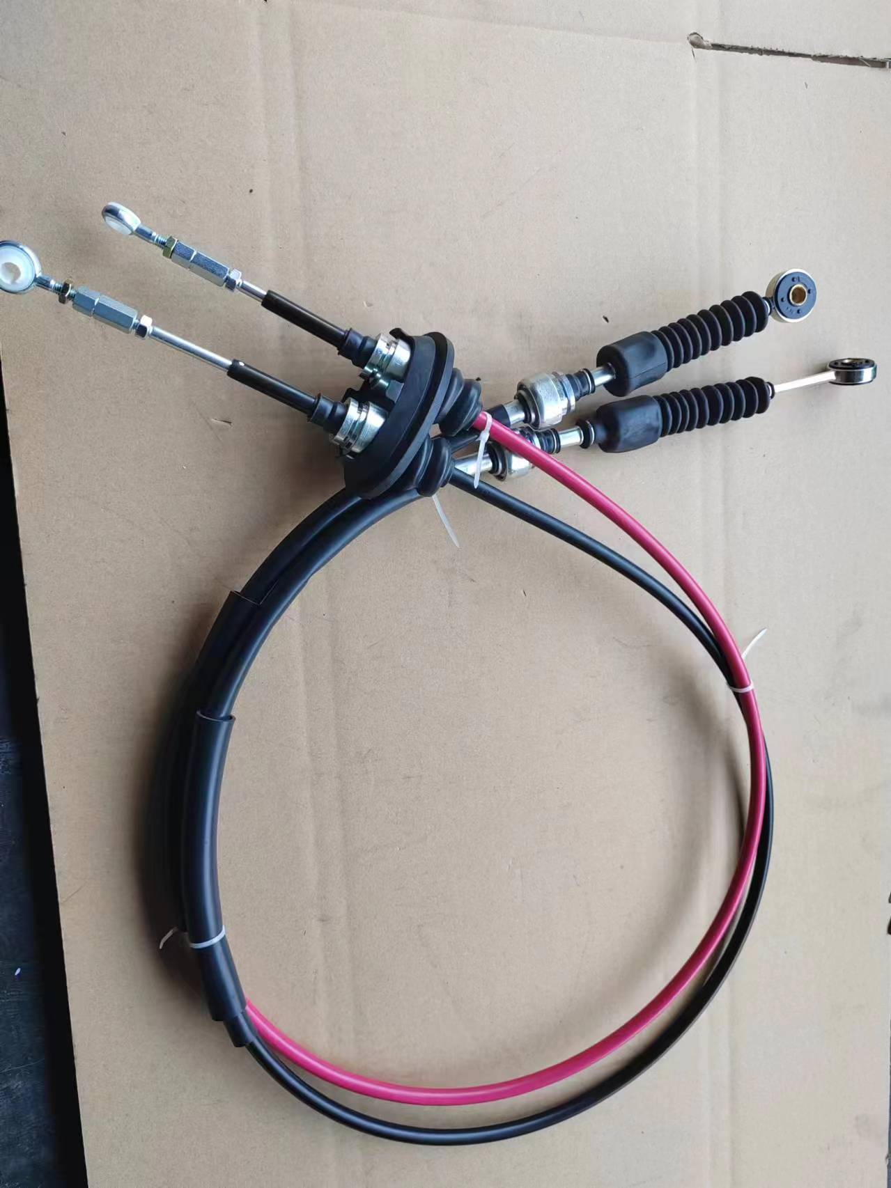
(hydraulic clutch line)
FAQS on hydraulic clutch line
以下是5组围绕液压离合器管路核心关键词的英文FAQ,采用HTML富文本格式:Q: What is a hydraulic clutch line used for?
A: A hydraulic clutch line transmits fluid pressure between the master cylinder and slave cylinder. It replaces mechanical linkage for smoother clutch operation. Proper installation prevents fluid leaks and air bubbles.
Q: Why choose a custom hydraulic clutch line?
A: Custom hydraulic clutch lines provide exact length specifications for unique vehicle modifications. They eliminate fitment issues in engine swaps or custom builds. Pre-bent configurations simplify installation for specific chassis layouts.
Q: How does a clutch slave cylinder hydraulic line function?
A: This line delivers pressurized fluid from the master cylinder to the clutch slave cylinder. It converts hydraulic pressure into mechanical movement to disengage the clutch. Damaged lines cause clutch engagement failure or fluid loss.
Q: Are universal hydraulic clutch lines adaptable?
A: Universal hydraulic clutch lines feature adjustable fittings for diverse applications. They suit vintage cars or modified transmissions lacking OEM parts. Must be trimmed and assembled to match specific routing requirements.
Q: What causes hydraulic clutch line failures?
A: Common failures include hose swelling from contaminated fluid or abrasion damage from improper routing. Steel braided lines resist degradation better than rubber. Regular inspections prevent sudden pressure loss during operation.
-
High Performance Throttle Cable Linkage for Precision MachineryNewsApr.16,2026
-
Ultimate Guide to Choosing a Quality carburetor throttle cableNewsApr.09,2026
-
Comprehensive Guide to the Dual Cable Throttle Assembly for Optimal PerformanceNewsApr.07,2026
-
The Importance of a Quality Throttle Cable Wire for Engine PerformanceNewsApr.04,2026
-
Understanding the Importance of a Manual Throttle Cable for Optimal PerformanceNewsMar.31,2026
-
Understanding the Critical Role of Throttle Rod Linkage in Engine PerformanceNewsMar.28,2026